
Applications & workpieces.
Explore the workpiece materials, shapes and production tasks suited to this equipment.

- Repeated component families with consistent loading orientation
- Cleaning between machining and assembly operations
- Connected spray washing, rinsing and drying stages
- Manual or mechanical infeed and outfeed
How the process works.

- 01Load
- 02Spray wash
- 03Rinse
- 04Air blow-off
- 05Hot-air dry
- 06Unload
Equipment details.
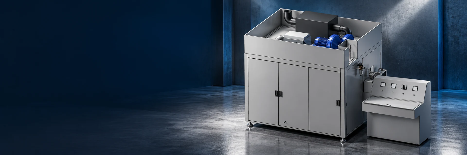
Conveyor washer layout with process enclosure and control console.

Equipment options.
Explore workpiece fixtures, process stages and handling options for your components.

| Equipment feature | Available arrangements | Your application |
|---|---|---|
| Workpiece clearance | Loading space for the part and its fixture | Belt width, usable width and process opening |
| Conveyor movement | Part spacing and speed | Required output and time in each process zone |
| Process stages | Washing, rinsing, blow-off and drying | Incoming contamination and required part condition |
| Line connections | Infeed, outfeed and control signals | Loading height, station stops and service access |
Connected stages for component washing, rinsing and drying.
Stable part presentation through the washer.
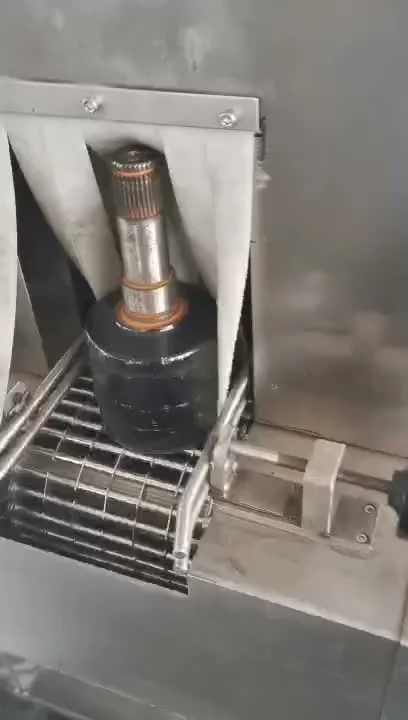
Workpiece supports and guide rails keep components in their loading orientation as they move along the conveyor. The loading space includes the component, fixture and clearance needed for washing and drainage.

Balance output with treatment time.
Part spacing and conveyor speed determine how often finished parts leave the system. The length of each process zone determines how long a component spends in that stage.
Together, these settings connect the required production output with washing, rinsing and drying time.
Connect the washer to adjacent stations.
Infeed height, outfeed direction and control signals connect the washer to the production line. The layout also provides access to liquid circuits, maintenance points and loading positions.
Set the loading pitch and output target
Define part spacing and orientation at the infeed and discharge. Agree the output interval separately from how long each part spends in treatment.
- Part pitch, loading height and transfer direction
- Required output and operating pattern
- Drainage, discharge temperature and dryness requirements
See the sequence
in motion.
Watch workpiece handling and equipment operations through the process sequence.
- Part and fixture dimensions in loading orientation
- Contamination, dryness and evaluation method
- Required output and loading pattern
- Available space, line height and interfaces
- Representative samples for process evaluation
Your equipment
questions, answered.
Find answers about materials, part handling and inspection or cleaning processes.

How are the cleaning stages selected?
Washing, rinsing, air blow-off and drying are selected for the incoming contamination and required finished part condition. Geometry, cleaning-liquid compatibility and the next production operation also influence the sequence.
Include any specified surface cleanliness and dryness requirements.
How much loading space does a part need?
Loading space includes the component, its supports or fixture, and the clearance required for treatment and transport. Belt width, usable loading width and the process opening are considered separately.
Show the part in its intended loading orientation, including spacing between components.
How is conveyor speed selected?
Conveyor speed works with part spacing and process-zone length to achieve the required output and treatment time. Washing and drying requirements guide the selected movement settings.
Provide the target parts per hour and the planned loading pattern.
What is the difference between output interval and treatment time?
Output interval is the time between finished parts leaving the machine. Treatment time is how long one component stays in a washing or drying zone. Several components can move through different zones at the same time.
Part spacing, conveyor speed and zone length connect output with treatment time.
When is indexed cleaning useful?
Indexed handling is considered when a component needs a fixed position or orientation at a cleaning stage. Fixtures locate the part while the sequence coordinates treatment and transfer.
The required station time, part changes and output guide the equipment arrangement.
Which stages can accompany ultrasonic cleaning?
Ultrasonic cleaning can be combined with rinsing, additional cleaning stages, air blow-off and hot-air drying. Workpiece transfer and drainage connect the stages.
The sequence is selected for the material, contamination and required finish.
How is cleaning performance evaluated?
Surface appearance, dryness and particulate cleanliness are evaluated using the method specified for the component. Photographs show the surface appearance; particle requirements use the specified sampling and measurement method.
Include the required measurement and acceptance criteria in your enquiry.
What should an enquiry for custom cleaning equipment include?
Include the part range, material, incoming contamination, required finish, output and loading preference. Add the available floor space, site services and connections to adjacent equipment.
Drawings and representative samples help develop the equipment proposal.
Can I view technical-cleanliness analysis documents?
Two technical-cleanliness analysis reports are available in the testing and documentation section. They include particle-size results, classifications and microscopy images.
Open the complete PDF to see the extraction and analysis information for each report.
Connect the details.
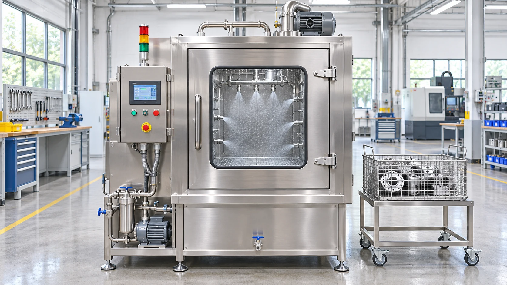
Industrial parts washers
Plan spray washing, rinsing, air blow-off and hot-air drying for machined parts. Compare handling options around contamination, part geometry and required output.
Explore the application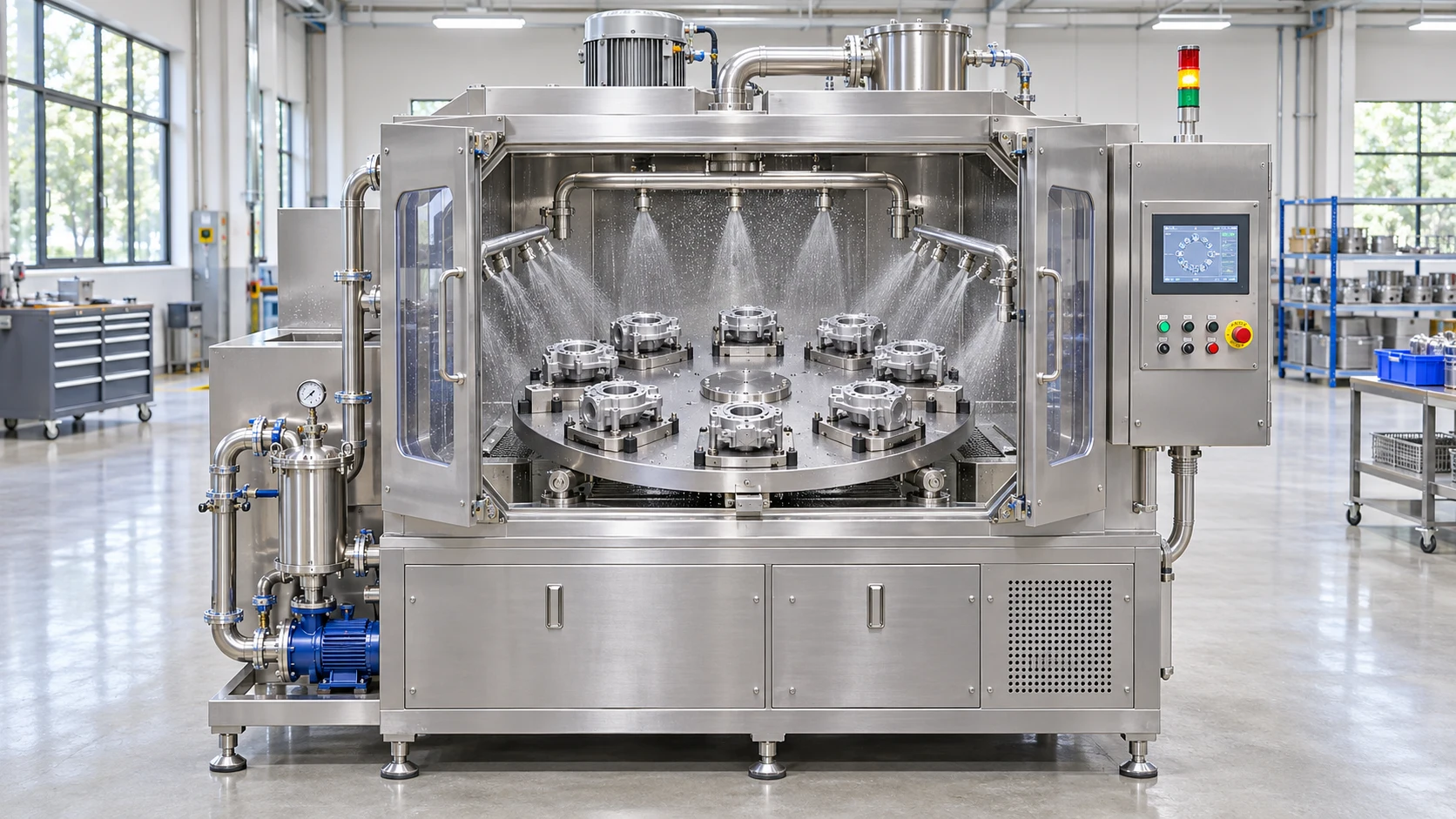
Indexing parts washers
Evaluate indexed parts washing when each component needs a defined position at each station. Specify fixtures, cycle timing and changeover needs.
Explore the application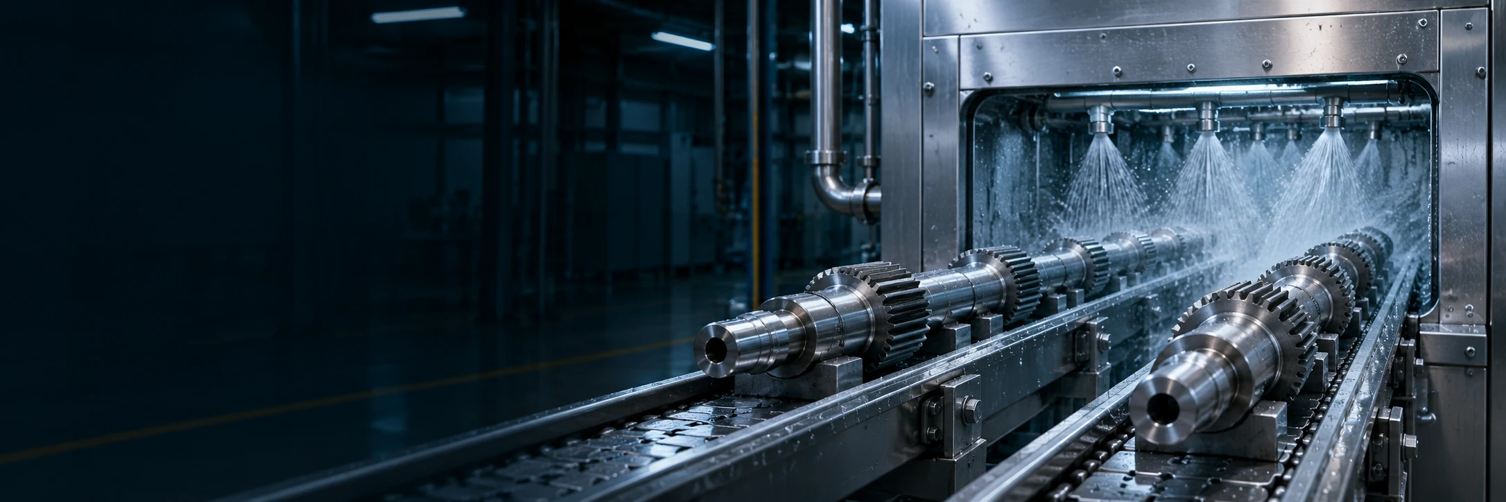
Planning a conveyor parts washing process
Plan conveyor parts washing from the incoming condition to drying and discharge. Define loading pitch, treatment time and required output separately.
Read the guide