
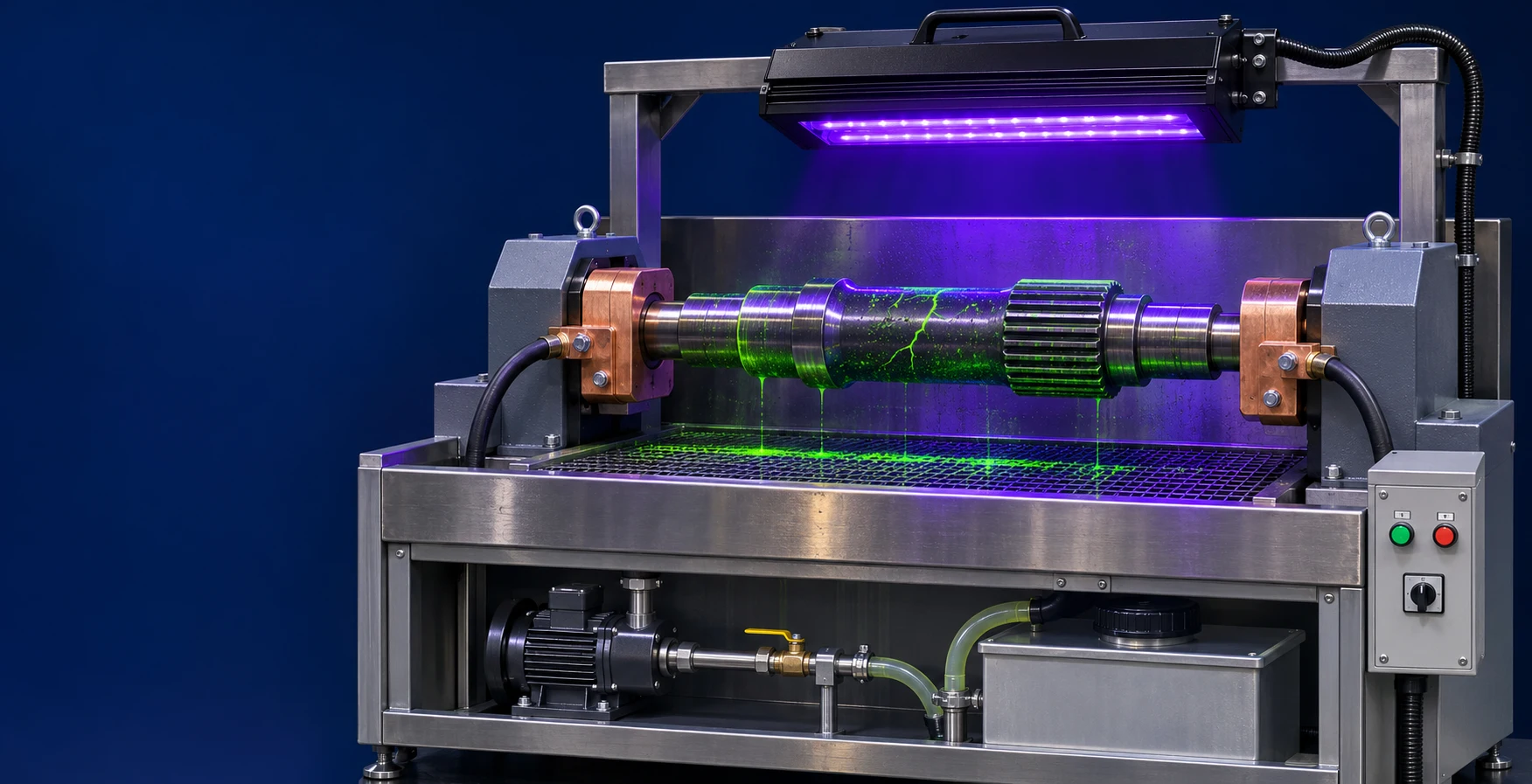
Applications & workpieces.
Explore the workpiece materials, shapes and production tasks suited to this equipment.

- Ferromagnetic shafts, rings and irregular components
- Inspection of machined and heat-treated parts
- Manual or mechanical loading
- Operator access for viewing fluorescent indications
How the process works.

- 01Load & clamp
- 02Magnetize
- 03Apply particles
- 04Present the part
- 05Operator inspection
Equipment details.
Magnetization equipment with a control panel and workpiece inspection enclosure.
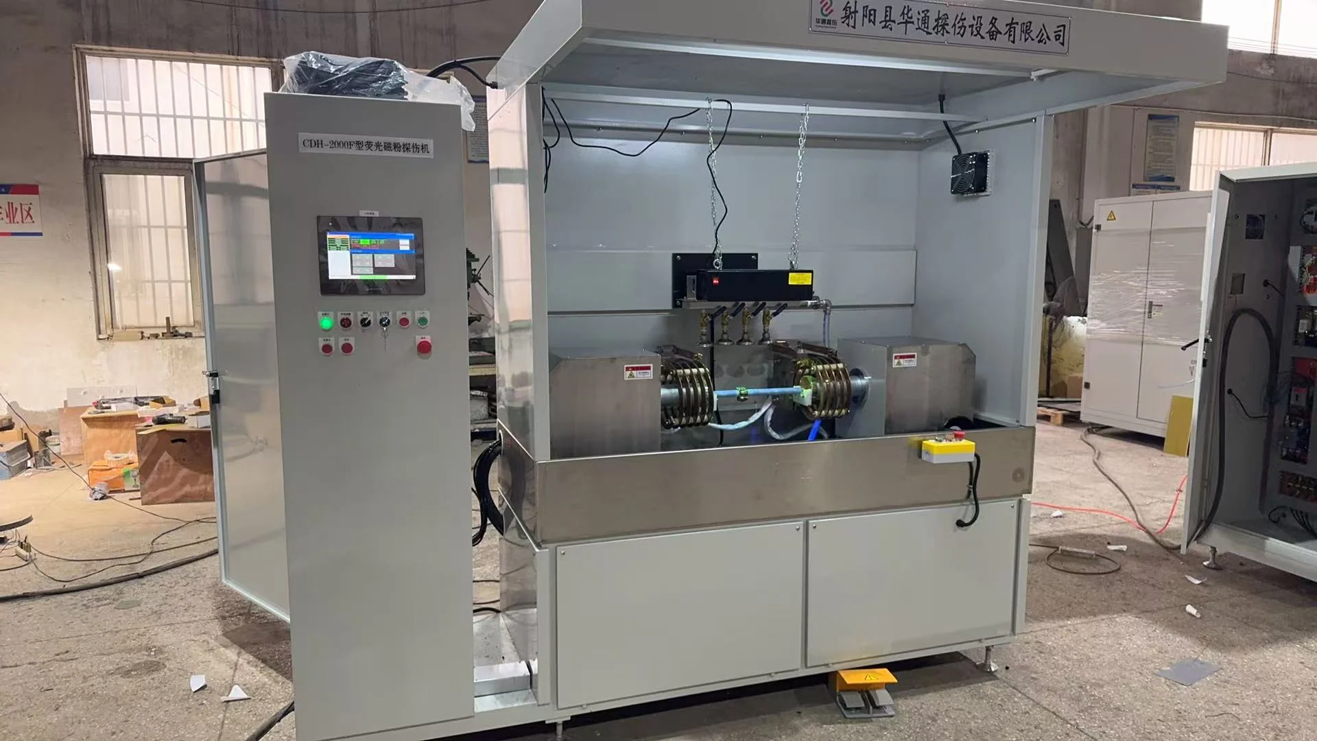
Equipment options.
Explore workpiece fixtures, process stages and handling options for your components.

| Equipment feature | Available arrangements | Your application |
|---|---|---|
| Workpiece range | Shaft, ring and irregular-part arrangements | Part dimensions, weight and inspection areas |
| Workpiece fixtures | End clamping, vertical positioning and pass-through arrangements | Contact points, support and access to inspection surfaces |
| Magnetization | Current and field direction matched to the inspection procedure | Material, geometry and required inspection coverage |
| Particle application | Spray or immersion | Surface coverage and workpiece orientation |
| Handling & inspection | Manual or mechanical transfer with operator inspection | Loading, viewing position and accepted/rejected part flow |
| Demagnetization | Residual-magnetism control after inspection | Required residual field, measurement points and next operation |
Inspection of ferromagnetic shafts, rings and machined components.
The operator examines fluorescent indications using the inspection procedure.
Inspection for your component geometry.
Shaft length, shoulders, ring sections and surface features influence the fixture and magnetization arrangement. Workpiece drawings help match the equipment to the surfaces that need inspection.
Fixtures support the component during magnetization and leave the operator access to view indications. Loading direction and part variations also guide fixture selection and changeover.

From loading to operator inspection.
The inspection sequence brings together loading, clamping, magnetization, particle application and transfer. The operator then examines the component and determines the result using the inspection procedure.
Production planning takes the full sequence into account, including loading, examination and unloading.

Discuss your inspection application.
Share your component drawings, material, inspection procedure and required output. These details help us prepare a proposal for the fixtures, handling and inspection sequence.
Specify the part range before the inspection station
Start with material, part dimensions and inspection surfaces. Then agree how the part will be clamped, magnetized and presented to the operator.
- Smallest and largest parts with drawings
- Inspection areas and applicable examination procedure
- Required output and manual or mechanical loading
See the sequence
in motion.
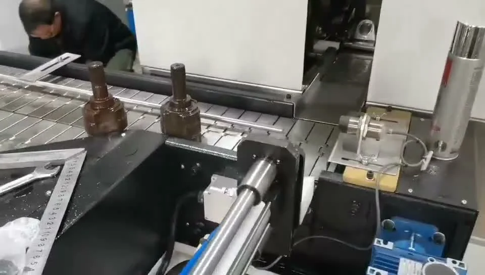
Watch workpiece handling and equipment operations through the process sequence.
- Material grade and manufacturing condition
- Part drawings, size range and mass
- Relevant inspection areas and applicable procedure
- Completed output target and handling arrangement
- Demagnetization requirement and site layout
Your equipment
questions, answered.
Find answers about materials, part handling and inspection or cleaning processes.
Which materials are suitable for magnetic particle inspection?
Magnetic particle inspection is used for ferromagnetic components, including suitable steel and iron parts. Aluminium, copper and other non-ferromagnetic materials require a different inspection method.
Include the material grade and manufacturing condition with your enquiry.
What component information is needed for an MPI system?
Send drawings showing the complete part range, dimensions, weight, shoulders and end features. Mark the surfaces that need inspection and any restrictions on clamping or electrical contact.
For multiple part sizes, include the smallest and largest variants.
How are the magnetization settings selected?
The material, component shape and inspection procedure guide the current type, field direction and magnetization settings. Include the required inspection areas and acceptance criteria with the workpiece drawings.
The fixture and magnetization arrangement are selected together for the component.
How does operator inspection fit into automated MPI?
The equipment can coordinate loading, clamping, magnetization, particle application and transfer. An operator examines the fluorescent indications and determines the result using the inspection procedure.
Production output includes the time for workpiece handling and operator inspection.
Can the equipment use manual or mechanical loading?
Manual loading, mechanical handling and production-line connections can be considered for the component and required output. Part orientation, fixtures and transfer height guide the loading arrangement.
Include the incoming and outgoing part flow with your line layout.
What information is needed for demagnetization?
Include the residual-field limit, units, measurement method and measurement points. Component material, previous magnetization and the next operation help select the process and handling.
For a new part family, representative components help evaluate the demagnetization process.
What drawings are useful for shaft inspection?
Include shaft length, diameter changes, shoulders, end features, weight and inspection areas. Add the material grade, manufacturing condition and intended loading direction.
Drawings for the full shaft range help plan fixtures and changeover.
Can one system inspect several ring sizes?
A shared arrangement can be considered across the complete ring range. Inner and outer diameters, thickness, weight and inspection surfaces guide fixtures, magnetization and operator access.
Provide the smallest and largest ring drawings, along with any section changes.
Connect the details.
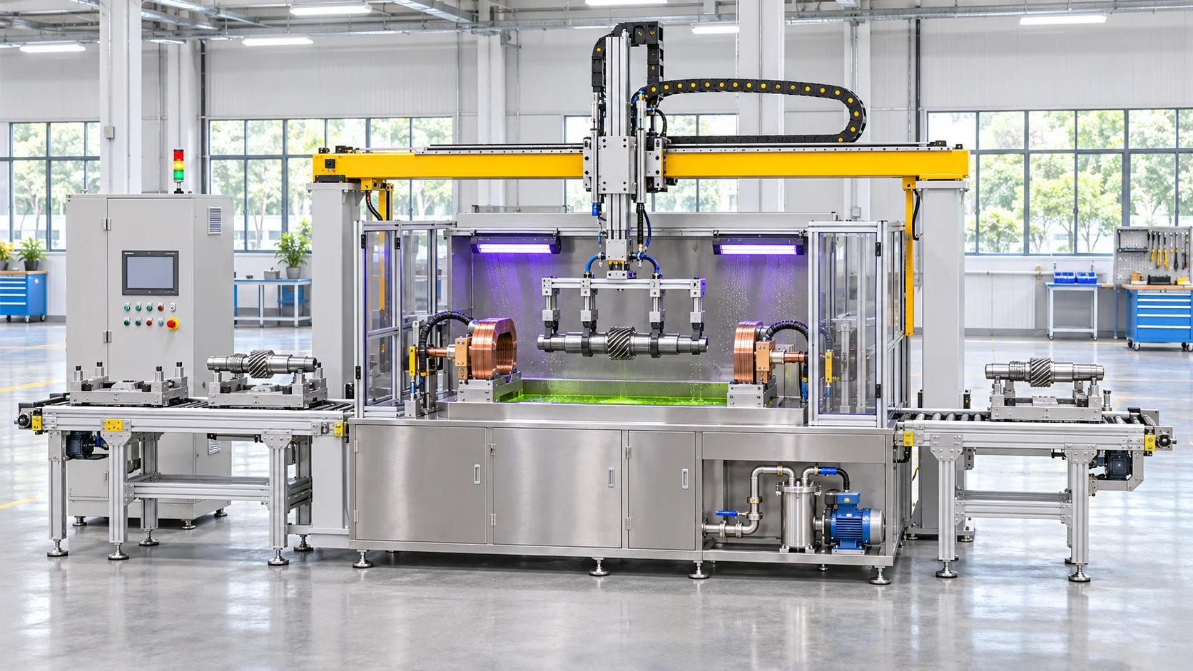
Automated magnetic particle inspection systems
Coordinate loading, clamping, magnetization and transfer around your workpiece range, line interfaces and operator inspection sequence.
Explore the application
Magnetic particle inspection for shafts
Specify shaft inspection around length, diameter, shoulders, fixture contact and access to the inspection surfaces on ferromagnetic parts.
Explore the application
Magnetic particle inspection of ring components
Evaluate fluorescent magnetic particle inspection for ferromagnetic rings. Use bore, outer diameter and inspection surfaces to plan handling and magnetization.
Explore the application