VDA 19.1 · 2 PAGES · PDF
Technical cleanliness analysis 01
VDA 19.1 cleanliness analysis with particle-size results and microscopy images.
Loading equipment information…
Home
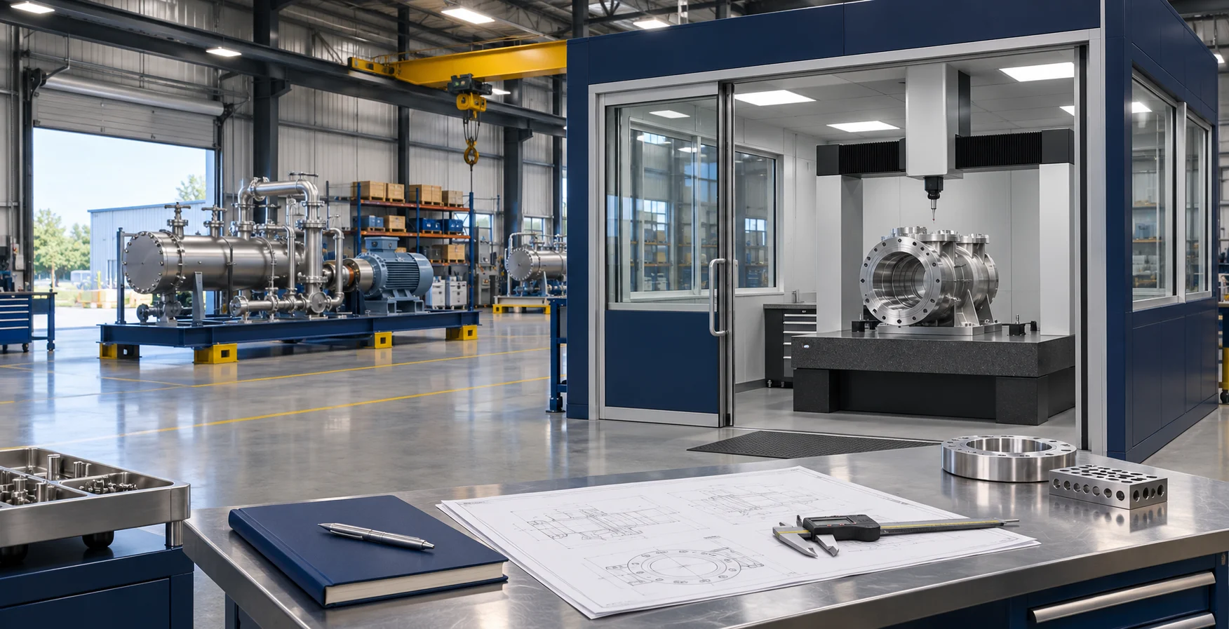
Engineering starts with the complete workpiece family: material, manufacturing condition, dimensions, weight and the surfaces that matter to the next operation. These inputs connect equipment selection with clamping, cleaning access, drainage and operator inspection.
For MPI, the inspection procedure and relevant surfaces guide magnetization and viewing access. For cleaning, incoming contamination, required dryness and the specified cleanliness measurement guide the treatment stages. Production output and loading then turn the selected process into a working equipment layout.
Start your equipment enquiry
Explore inspection and cleaning routes. Follow each sequence from loading to the part condition needed by the next operation.
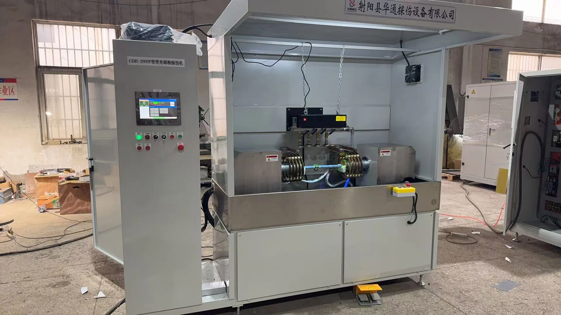
For ferromagnetic components, coordinate fixture positioning, magnetization and fluorescent-particle application with an operator viewing station.
Inspection surfaces, viewing access, handling and the component disposition are planned as one workflow.

Fixtures locate the component and make the important surfaces accessible. Support positions, contact restrictions and loading direction are considered across the part range, including shoulders, bores, recesses and irregular features.
Inspection fixtures also leave access for magnetization and operator viewing. Cleaning carriers support the part while allowing liquid access and drainage. Where several variants share equipment, fixture changes and the workpiece-and-fixture envelope are planned together.

A cleaning sequence connects the incoming contamination to the finished part condition. Spray or ultrasonic treatment is considered with rinsing, air blow-off and hot-air drying. Geometry and loading influence where liquid reaches and where it remains between stages.
Circulation, filtration, cleaning-liquid compatibility and access for maintenance belong in the process discussion. Surface appearance, dryness and particulate cleanliness use the evaluation method specified for the component. Sample testing helps select a sequence using representative incoming parts.

Equipment interfaces join incoming presentation, treatment and onward transfer. Loading height, part-ready positions and transfer direction connect the machine to adjacent stations. The line discussion also covers the behavior required when a station or connected machine stops.
Share the existing control arrangement and the required start, stop and transfer signals. Include the responsibilities for fixtures, conveyors and connected equipment in the proposal. The result is a mechanical and control interface plan that each project team can work from.

The working layout includes loading, operation, inspection and service access in addition to the machine footprint. Part containers, fixture changes and maintenance tasks influence the space around the installation.
Electrical supply, water, compressed air and drainage are planned for the installation location. For cleaning equipment, access to tanks, liquid circuits, filtration and drying assemblies supports operation and maintenance. A marked site drawing makes these connections easier to coordinate.
Bring component, production and site requirements into one proposal. Each input has a practical role in the equipment design.
| Engineering input | Information to prepare | Equipment decision |
|---|---|---|
| Component range | Material, geometry, weight and variants | Fixtures, loading clearance and process access |
| Required result | Inspection procedure or cleaning/dryness requirement | Treatment route and evaluation method |
| Production output | Parts per hour, shifts, loading pattern and part mix | Transfer, treatment and operator time |
| Line interfaces | Loading height, direction and control signals | Mechanical handoff and station behavior |
| Site services | Electrical supply, water, air and drainage | Connection points and working clearances |
| Acceptance | Sample parts, operating conditions and evaluation criteria | Factory and site equipment checks |
The technical agreement brings the workpiece range, process sequence, fixtures, loading and line interfaces into one equipment specification. The proposal also records required output, site services and the inspection or cleanliness evaluation method.
Factory acceptance and site acceptance use the agreed components, operating conditions and checks. For MPI, the sequence includes operator inspection. For cleaning, surface condition, dryness and any specified particle measurements are evaluated using the agreed method. Delivery, installation and commissioning responsibilities are planned with the project.
Explore the project steps
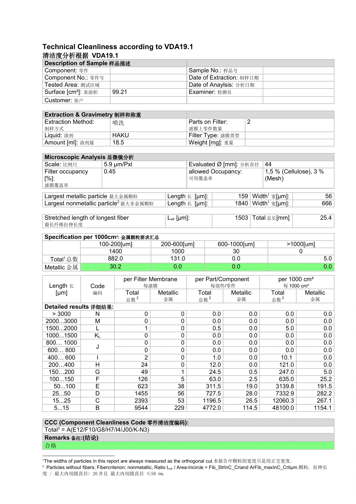
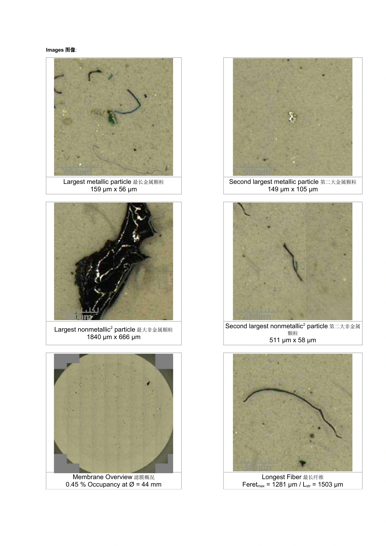
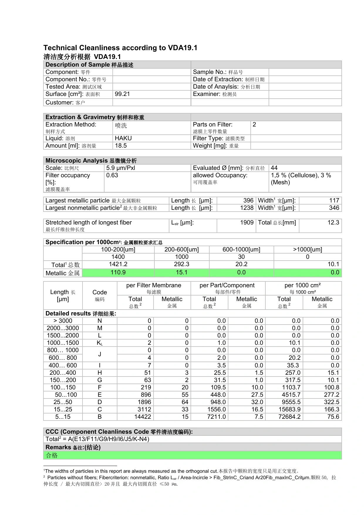
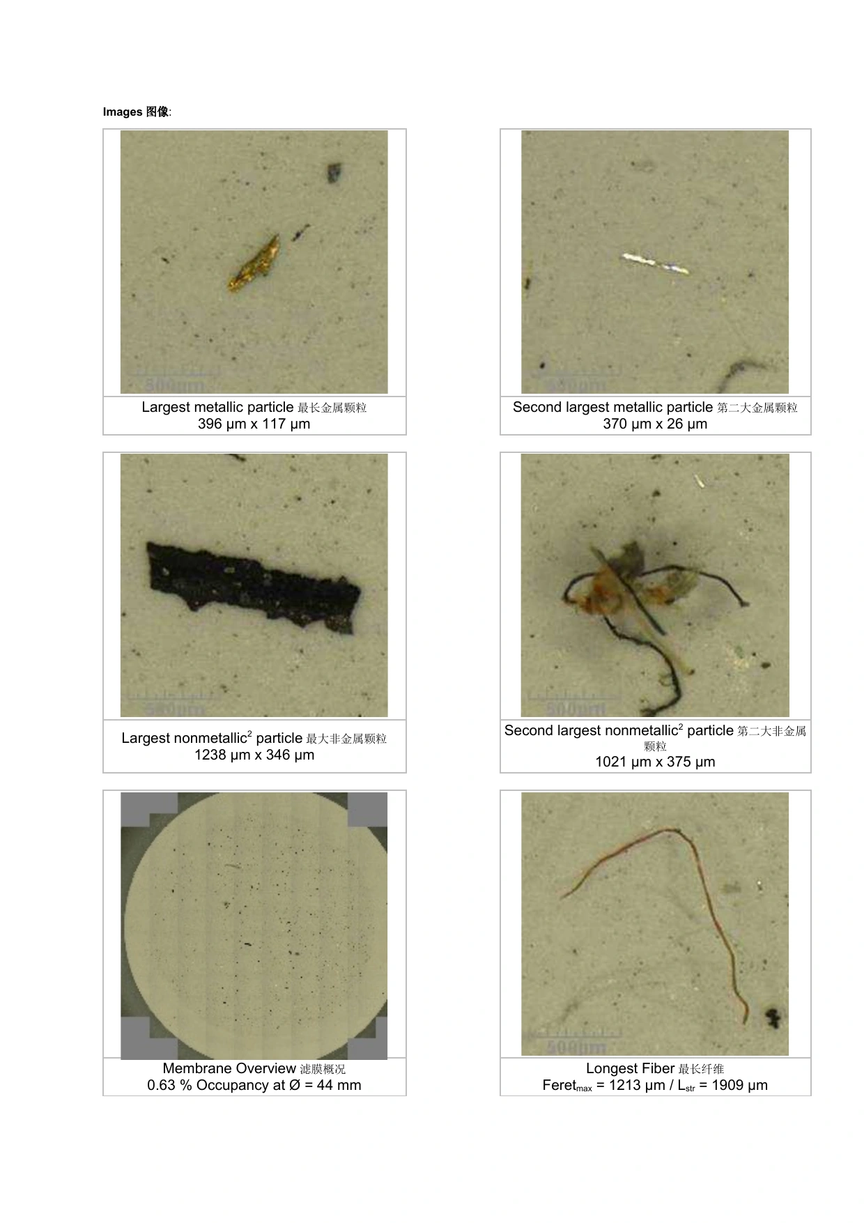
Technical-cleanliness analysis brings particle sizes, classifications and microscopy images together. Open the original reports to explore the measurements and analysis format.
VDA 19.1 cleanliness analysis with particle-size results and microscopy images.
VDA 19.1 cleanliness analysis with particle-size results and microscopy images.
Explore process planning, fixtures, output, line interfaces and acceptance.

Include component drawings, material, weight, manufacturing condition, target output and the required inspection or cleaning result. Add loading preferences, floor space and available site services.
The smallest and largest variants help plan fixture changes and workpiece clearance.
The process starts with the workpiece and the condition required by the next operation. MPI combines loading, magnetization, particle application and operator inspection. Cleaning brings together the required washing, rinsing, liquid removal and drying stages.
Sample testing helps evaluate the proposed sequence with production components.
Fixture planning addresses support points, orientation, contact restrictions, process access and changeover. For inspection it also considers the required viewing access; for cleaning it considers drainage and access to the surfaces being treated.
Include drawings for variants that change the support or locating positions.
Output planning covers loading, transfer, processing, operator inspection where required, and unloading. Conveyor spacing and zone length connect output with time in each treatment stage.
Provide the desired parts per hour, shift pattern and expected part mix.
Describe part-ready and transfer signals, station start/stop behavior and the response expected when adjacent equipment stops. Include the existing line-control arrangement and who supplies each interface.
These details are brought into the equipment proposal and technical agreement.
Electrical supply, water, compressed air, drainage and access for operation and maintenance affect the installation plan. Cleaning layouts also include access to liquids, filtration and drying equipment.
Share a floor plan with loading height and service-connection positions.
Holes, recesses and workpiece orientation influence where liquid remains after washing. Air blow-off and hot-air drying are selected alongside loading and transfer to achieve the required finished condition.
Include the surfaces and cavities that are important to the next operation.
The technical agreement brings together the component range, process sequence, loading method, output requirements and evaluation method. Factory and site checks use the agreed parts and operating conditions.
For cleanliness measurements, include the sampling and analysis method with the required limits.
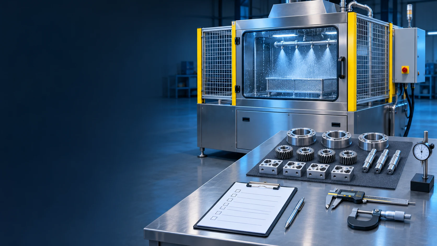
Use a printable checklist to plan factory and site acceptance. Define samples, test conditions, equipment interfaces, evidence and actions before signing off.
Read the guide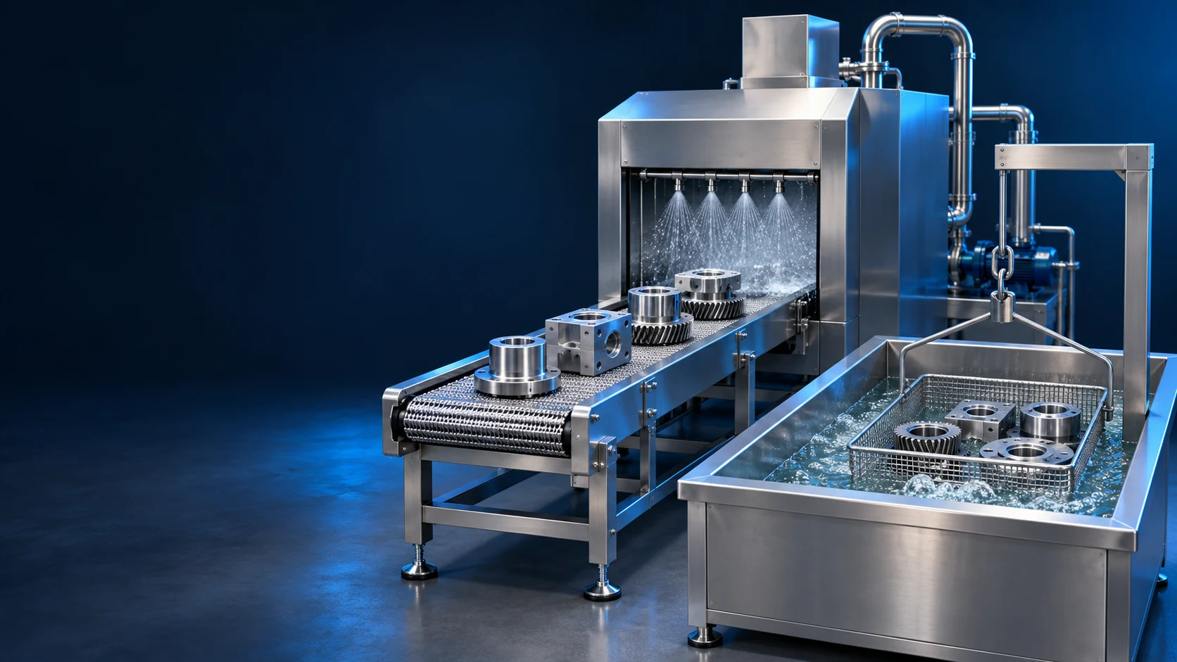
Compare spray and ultrasonic cleaning separately from conveyor and indexed handling. Use your part geometry, contamination, production load and required result.
Read the guide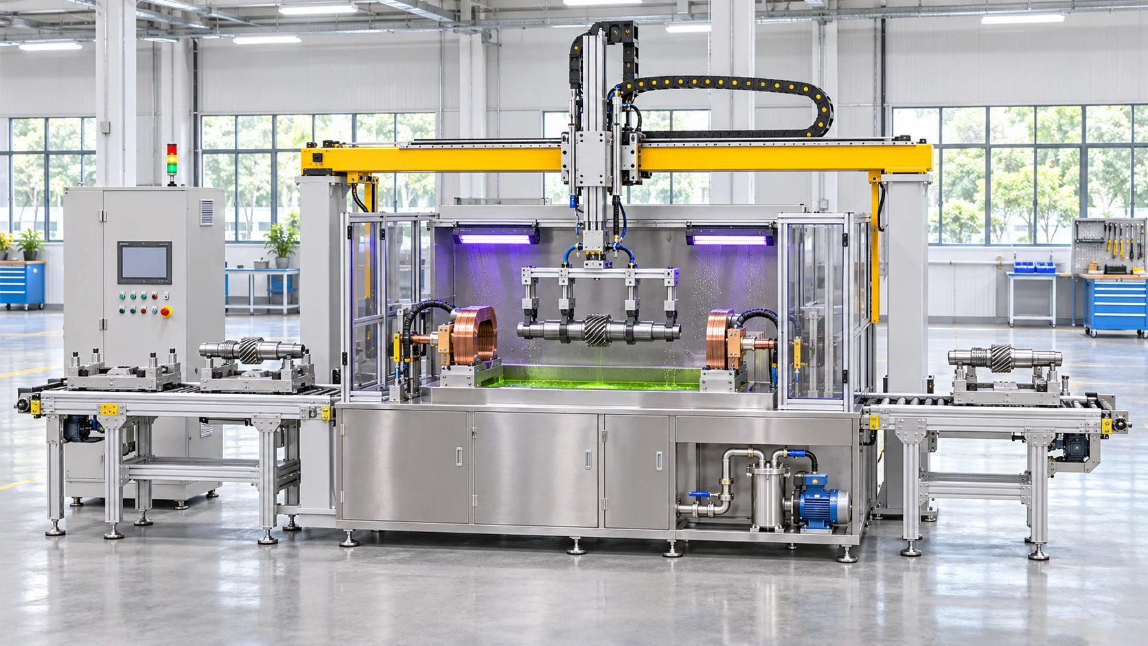
Coordinate loading, clamping, magnetization and transfer around your workpiece range, line interfaces and operator inspection sequence.
Explore the applicationTell us about your components, production targets and inspection or cleaning requirements.
Prepare your project brief