To enquire about magnetic particle inspection equipment, prepare the material grade, component drawings, inspection procedure, required output and loading method. Together, these details guide fixtures, magnetization and the operator inspection station.
Material and manufacturing condition

Magnetic particle inspection is used for ferromagnetic components. Include the material grade and the stage at which the part will be inspected, such as after machining or heat treatment. Mark the surfaces that need inspection on the drawing.
The inspection procedure guides the magnetization arrangement and examination of indications. Share the applicable procedure and acceptance criteria with the enquiry so the equipment proposal can address the required inspection areas.
Component drawings and part range

For shafts, show the length, diameter changes, shoulders, end features and weight. These details guide supports, clamping and loading. For ring components, include inner diameter, outer diameter, thickness and the surfaces that require inspection.
Where several parts will use one system, include drawings for the smallest and largest variants. Highlight changes in contact areas, support positions and loading orientation. The part mix and frequency of changeover help select fixtures and workpiece handling.
Provide any surface-contact restrictions alongside the drawings. This makes it easier to plan clamping and magnetization while preserving access for operator inspection.
Loading, magnetization and operator inspection

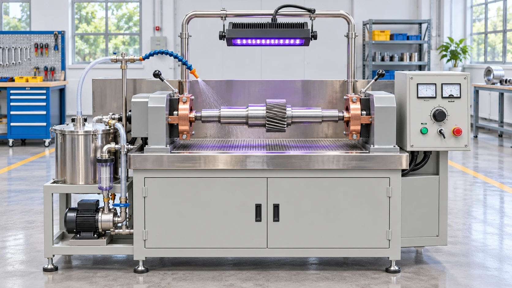
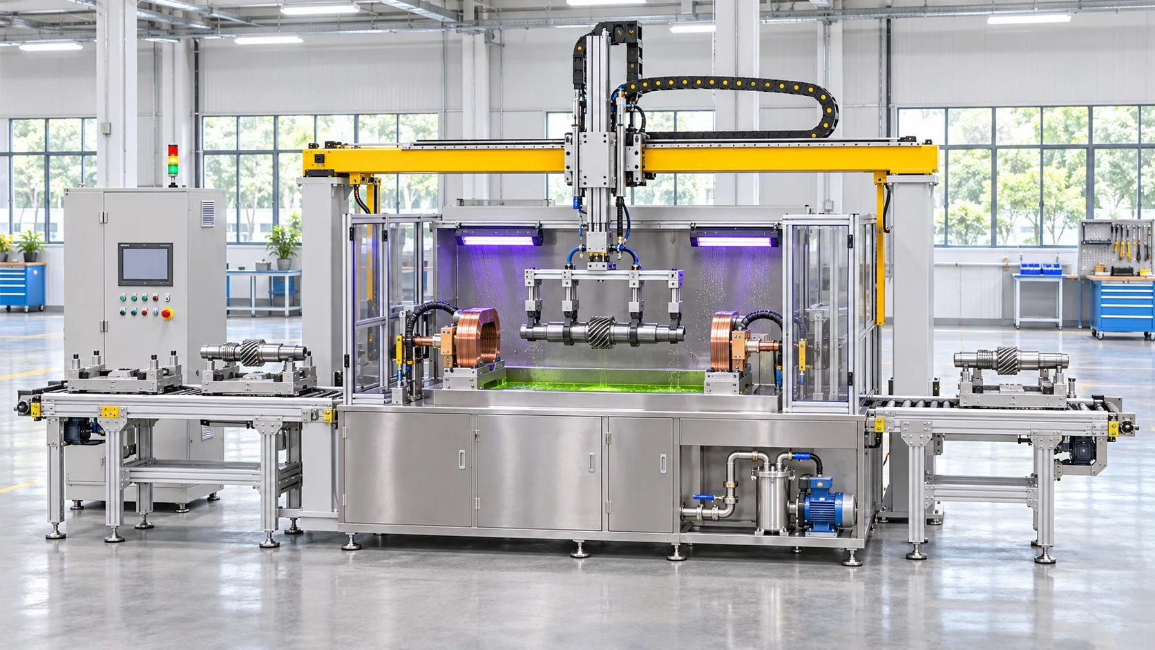
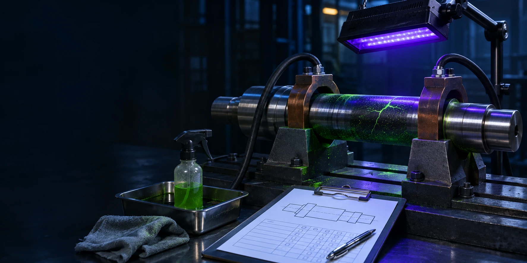
An inspection workflow combines part loading, locating, clamping, magnetization, particle application, transfer and operator inspection. Mechanical handling can coordinate component movement, while the operator examines fluorescent indications using the inspection procedure.
Include the target parts per hour and the planned staffing. The production sequence includes loading, inspection and unloading, as well as the treatment steps. Describe how components arrive at the station and where accepted and rejected parts should go next.
For a connected line, add the loading height, transfer direction and control signals. These details help position the viewing station and coordinate movement between machines.
Demagnetization and residual-field measurement

If the component needs demagnetization after inspection, include the residual-field limit and its units. Specify the measurement points and method used to assess the part.
The component material, geometry and previous magnetization guide the demagnetization arrangement. Describe the next manufacturing operation and any restrictions on workpiece movement. Demagnetization can then be considered alongside part handling and the inspection workflow.
Production layout and sample parts

Share the available floor space, loading direction, electrical supply and other site services. Allow room for operation, fixture changes and maintenance. A layout drawing helps connect the inspection station with incoming and outgoing equipment.
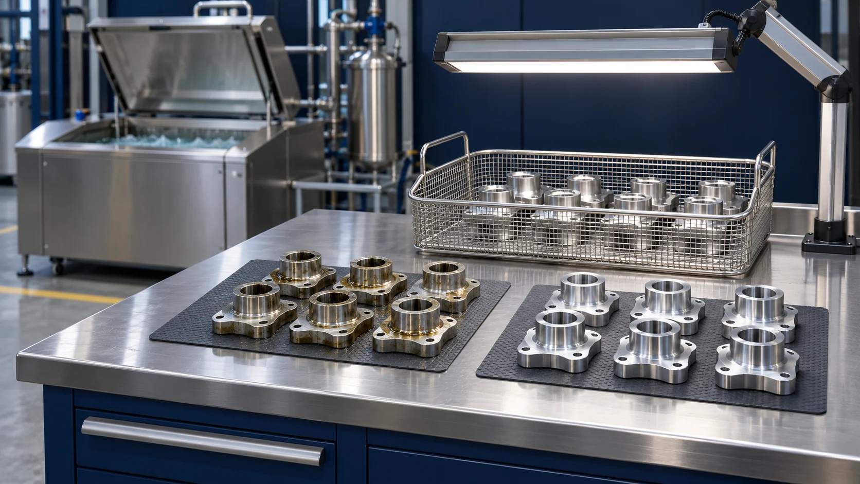
Representative samples help evaluate workpiece positioning, magnetization and viewing access. Include the variants that affect clamping or changeover, along with the required inspection procedure. The findings support the proposed fixtures and process sequence.
Prepare your enquiry

Bring together the material grade, drawings, component weight, inspection areas, procedure, output target and loading preference. Add demagnetization requirements and site information where relevant. Further details can be added as the equipment proposal develops.
Explore magnetic particle inspection equipment, learn about automated handling, or prepare your project enquiry.
Ready to explore equipment for your parts?
Bring your drawings, process requirements and production targets into your enquiry.
Organize your requirements